Wednesday, 2 October 2013

IP ADDRESSING


An IP address is a 32-bit number that uniquely identifies a host (computer or other device, such as a printer or router) on a TCP/IP network.


IP addresses are normally expressed in dotted-decimal format, with four numbers separated by periods, such as 192.168.123.132. To understand how subnet masks are used to distinguish between hosts, networks, and subnetworks, examine an IP address in binary notation.


For example, the dotted-decimal IP address 192.168.123.132 is (in binary notation) the 32 bit number 110000000101000111101110000100. This number may be hard to make sense of, so divide it into four parts of eight binary digits.


These eight bit sections are known as octets. The example IP address, then, becomes 11000000.10101000.01111011.10000100. This number only makes a little more sense, so for most uses, convert the binary address into dotted-decimal format (192.168.123.132). The decimal numbers separated by periods are the octets converted from binary to decimal notation.


For a TCP/IP wide area network (WAN) to work efficiently as a collection of networks, the routers that pass packets of data between networks do not know the exact location of a host for which a packet of information is destined. Routers only know what network the host is a member of and use information stored in their route table to determine how to get the packet to the destination host's network. After the packet is delivered to the destination's network, the packet is delivered to the appropriate host.


For this process to work, an IP address has two parts. The first part of an IP address is used as a network address, the last part as a host address. If you take the example 192.168.123.132 and divide it into these two parts you get the following:

   192.168.123.132   Network
               
   0.0.0.132 host 
-or-
   192.168.123.0 - network address.
   0.0.0.132     - host address.
    

Subnet mask

The second item, which is required for TCP/IP to work, is the subnet mask. The subnet mask is used by the TCP/IP protocol to determine whether a host is on the local subnet or on a remote network.

In TCP/IP, the parts of the IP address that are used as the network and host addresses are not fixed, so the network and host addresses above cannot be determined unless you have more information. This information is supplied in another 32-bit number called a subnet mask. In this example, the subnet mask is 255.255.255.0. It is not obvious what this number means unless you know that 255 in binary notation equals 11111111; so, the subnet mask is:
   11111111.11111111.11111111.0000000
    
Lining up the IP address and the subnet mask together, the network and host portions of the address can be separated:
   11000000.10101000.01111011.10000100 -- IP address (192.168.123.132)
   11111111.11111111.11111111.00000000 -- Subnet mask (255.255.255.0)
    
The first 24 bits (the number of ones in the subnet mask) are identified as the network address, with the last 8 bits (the number of remaining zeros in the subnet mask) identified as the host address. This gives you the following:
   11000000.10101000.01111011.00000000 -- Network address (192.168.123.0)
   00000000.00000000.00000000.10000100 -- Host address (000.000.000.132)
    
So now you know, for this example using a 255.255.255.0 subnet mask, that the network ID is 192.168.123.0, and the host address is 0.0.0.132. When a packet arrives on the 192.168.123.0 subnet (from the local subnet or a remote network), and it has a destination address of 192.168.123.132, your computer will receive it from the network and process it.

Almost all decimal subnet masks convert to binary numbers that are all ones on the left and all zeros on the right. Some other common subnet masks are:
   Decimal                 Binary
   255.255.255.192         1111111.11111111.1111111.11000000
   255.255.255.224         1111111.11111111.1111111.11100000
    
Internet RFC 1878 (available from http://www.internic.net ) describes the valid subnets and subnet masks that can be used on TCP/IP networks.

Network classes

Internet addresses are allocated by the InterNIC (http://www.internic.net ), the organization that administers the Internet. These IP addresses are divided into classes. The most common of these are classes A, B, and C. Classes D and E exist, but are not generally used by end users. Each of the address classes has a different default subnet mask. You can identify the class of an IP address by looking at its first octet. Following are the ranges of Class A, B, and C Internet addresses, each with an example address:
  • Class A networks use a default subnet mask of 255.0.0.0 and have 0-127 as their first octet. The address 10.52.36.11 is a class A address. Its first octet is 10, which is between 1 and 126, inclusive.
  • Class B networks use a default subnet mask of 255.255.0.0 and have 128-191 as their first octet. The address 172.16.52.63 is a class B address. Its first octet is 172, which is between 128 and 191, inclusive.
  • Class C networks use a default subnet mask of 255.255.255.0 and have 192-223 as their first octet. The address 192.168.123.132 is a class C address. Its first octet is 192, which is between 192 and 223, inclusive.
In some scenarios, the default subnet mask values do not fit the needs of the organization, because of the physical topology of the network, or because the numbers of networks (or hosts) do not fit within the default subnet mask restrictions. The next section explains how networks can be divided using subnet masks.

Subnetting

A Class A, B, or C TCP/IP network can be further divided, or subnetted, by a system administrator. This becomes necessary as you reconcile the logical address scheme of the Internet (the abstract world of IP addresses and subnets) with the physical networks in use by the real world.


A system administrator who is allocated a block of IP addresses may be administering networks that are not organized in a way that easily fits these addresses. For example, you have a wide area network with 150 hosts on three networks (in different cities) that are connected by a TCP/IP router. Each of these three networks has 50 hosts. You are allocated the class C network 192.168.123.0. (For illustration, this address is actually from a range that is not allocated on the Internet.) This means that you can use the addresses 192.168.123.1 to 192.168.123.254 for your 150 hosts.


Two addresses that cannot be used in your example are 192.168.123.0 and 192.168.123.255 because binary addresses with a host portion of all ones and all zeros are invalid. The zero address is invalid because it is used to specify a network without specifying a host. The 255 address (in binary notation, a host address of all ones) is used to broadcast a message to every host on a network. Just remember that the first and last address in any network or subnet cannot be assigned to any individual host.


You should now be able to give IP addresses to 254 hosts. This works fine if all 150 computers are on a single network. However, your 150 computers are on three separate physical networks. Instead of requesting more address blocks for each network, you divide your network into subnets that enable you to use one block of addresses on multiple physical networks.


In this case, you divide your network into four subnets by using a subnet mask that makes the network address larger and the possible range of host addresses smaller. In other words, you are 'borrowing' some of the bits usually used for the host address, and using them for the network portion of the address. The subnet mask 255.255.255.192 gives you four networks of 62 hosts each. This works because in binary notation, 255.255.255.192 is the same as 1111111.11111111.1111111.11000000. The first two digits of the last octet become network addresses, so you get the additional networks 00000000 (0), 01000000 (64), 10000000 (128) and 11000000 (192). (Some administrators will only use two of the subnetworks using 255.255.255.192 as a subnet mask. For more information on this topic, see RFC 1878.) In these four networks, the last 6 binary digits can be used for host addresses.


Using a subnet mask of 255.255.255.192, your 192.168.123.0 network then becomes the four networks 192.168.123.0, 192.168.123.64, 192.168.123.128 and 192.168.123.192. These four networks would have as valid host addresses:

192.168.123.1-62
192.168.123.65-126
192.168.123.129-190
192.168.123.193-254
Remember, again, that binary host addresses with all ones or all zeros are invalid, so you cannot use addresses with the last octet of 0, 63, 64, 127, 128, 191, 192, or 255.


You can see how this works by looking at two host addresses, 192.168.123.71 and 192.168.123.133. If you used the default Class C subnet mask of 255.255.255.0, both addresses are on the 192.168.123.0 network. However, if you use the subnet mask of 255.255.255.192, they are on different networks; 192.168.123.71 is on the 192.168.123.64 network, 192.168.123.133 is on the 192.168.123.128 network.

Default gateways

If a TCP/IP computer needs to communicate with a host on another network, it will usually communicate through a device called a router. In TCP/IP terms, a router that is specified on a host, which links the host's subnet to other networks, is called a default gateway. This section explains how TCP/IP determines whether or not to send packets to its default gateway to reach another computer or device on the network.


When a host attempts to communicate with another device using TCP/IP, it performs a comparison process using the defined subnet mask and the destination IP address versus the subnet mask and its own IP address. The result of this comparison tells the computer whether the destination is a local host or a remote host.


If the result of this process determines the destination to be a local host, then the computer will simply send the packet on the local subnet. If the result of the comparison determines the destination to be a remote host, then the computer will forward the packet to the default gateway defined in its TCP/IP properties. It is then the responsibility of the router to forward the packet to the correct subnet.

OSI LAYERS


       The Open Systems Interconnect (OSI) model has seven layers. This article describes and explains them, beginning with the 'lowest' in the hierarchy (the physical) and proceeding to the 'highest' (the application). The layers are stacked this way:
  • Application
  • Presentation
  • Session
  • Transport
  • Network
  • Data Link
  • Physical

PHYSICAL LAYER

The physical layer, the lowest layer of the OSI model, is concerned with the transmission and reception of the unstructured raw bit stream over a physical medium. It describes the electrical/optical, mechanical, and functional interfaces to the physical medium, and carries the signals for all of the higher layers. It provides:
  • Data encoding: modifies the simple digital signal pattern (1s and 0s) used by the PC to better accommodate the characteristics of the physical medium, and to aid in bit and frame synchronization. It determines:

    • What signal state represents a binary 1
    • How the receiving station knows when a "bit-time" starts
    • How the receiving station delimits a frame
  • Physical medium attachment, accommodating various possibilities in the medium:

    • Will an external transceiver (MAU) be used to connect to the medium?
    • How many pins do the connectors have and what is each pin used for?
  • Transmission technique: determines whether the encoded bits will be transmitted by baseband (digital) or broadband (analog) signaling.
  • Physical medium transmission: transmits bits as electrical or optical signals appropriate for the physical medium, and determines:

    • What physical medium options can be used
    • How many volts/db should be used to represent a given signal state, using a given physical medium

DATA LINK LAYER

The data link layer provides error-free transfer of data frames from one node to another over the physical layer, allowing layers above it to assume virtually error-free transmission over the link. To do this, the data link layer provides: 

  • Link establishment and termination: establishes and terminates the logical link between two nodes.
  • Frame traffic control: tells the transmitting node to "back-off" when no frame buffers are available.
  • Frame sequencing: transmits/receives frames sequentially.
  • Frame acknowledgment: provides/expects frame acknowledgments. Detects and recovers from errors that occur in the physical layer by retransmitting non-acknowledged frames and handling duplicate frame receipt.
  • Frame delimiting: creates and recognizes frame boundaries.
  • Frame error checking: checks received frames for integrity.
  • Media access management: determines when the node "has the right" to use the physical medium.

NETWORK LAYER

The network layer controls the operation of the subnet, deciding which physical path the data should take based on network conditions, priority of service, and other factors. It provides: 

  • Routing: routes frames among networks.
  • Subnet traffic control: routers (network layer intermediate systems) can instruct a sending station to "throttle back" its frame transmission when the router's buffer fills up.
  • Frame fragmentation: if it determines that a downstream router's maximum transmission unit (MTU) size is less than the frame size, a router can fragment a frame for transmission and re-assembly at the destination station.
  • Logical-physical address mapping: translates logical addresses, or names, into physical addresses.
  • Subnet usage accounting: has accounting functions to keep track of frames forwarded by subnet intermediate systems, to produce billing information.

Communications Subnet

The network layer software must build headers so that the network layer software residing in the subnet intermediate systems can recognize them and use them to route data to the destination address. 

This layer relieves the upper layers of the need to know anything about the data transmission and intermediate switching technologies used to connect systems. It establishes, maintains and terminates connections across the intervening communications facility (one or several intermediate systems in the communication subnet). 

In the network layer and the layers below, peer protocols exist between a node and its immediate neighbor, but the neighbor may be a node through which data is routed, not the destination station. The source and destination stations may be separated by many intermediate systems.

TRANSPORT LAYER

The transport layer ensures that messages are delivered error-free, in sequence, and with no losses or duplications. It relieves the higher layer protocols from any concern with the transfer of data between them and their peers. 

The size and complexity of a transport protocol depends on the type of service it can get from the network layer. For a reliable network layer with virtual circuit capability, a minimal transport layer is required. If the network layer is unreliable and/or only supports datagrams, the transport protocol should include extensive error detection and recovery. 

The transport layer provides:
  • Message segmentation: accepts a message from the (session) layer above it, splits the message into smaller units (if not already small enough), and passes the smaller units down to the network layer. The transport layer at the destination station reassembles the message.
  • Message acknowledgment: provides reliable end-to-end message delivery with acknowledgments.
  • Message traffic control: tells the transmitting station to "back-off" when no message buffers are available.
  • Session multiplexing: multiplexes several message streams, or sessions onto one logical link and keeps track of which messages belong to which sessions (see session layer).
Typically, the transport layer can accept relatively large messages, but there are strict message size limits imposed by the network (or lower) layer. Consequently, the transport layer must break up the messages into smaller units, or frames, prepending a header to each frame. 

The transport layer header information must then include control information, such as message start and message end flags, to enable the transport layer on the other end to recognize message boundaries. In addition, if the lower layers do not maintain sequence, the transport header must contain sequence information to enable the transport layer on the receiving end to get the pieces back together in the right order before handing the received message up to the layer above.

End-to-end layers

Unlike the lower "subnet" layers whose protocol is between immediately adjacent nodes, the transport layer and the layers above are true "source to destination" or end-to-end layers, and are not concerned with the details of the underlying communications facility. Transport layer software (and software above it) on the source station carries on a conversation with similar software on the destination station by using message headers and control messages.

SESSION LAYER

The session layer allows session establishment between processes running on different stations. It provides: 

  • Session establishment, maintenance and termination: allows two application processes on different machines to establish, use and terminate a connection, called a session.
  • Session support: performs the functions that allow these processes to communicate over the network, performing security, name recognition, logging, and so on.

PRESENTATION LAYER

The presentation layer formats the data to be presented to the application layer. It can be viewed as the translator for the network. This layer may translate data from a format used by the application layer into a common format at the sending station, then translate the common format to a format known to the application layer at the receiving station. 

The presentation layer provides: 

  • Character code translation: for example, ASCII to EBCDIC.
  • Data conversion: bit order, CR-CR/LF, integer-floating point, and so on.
  • Data compression: reduces the number of bits that need to be transmitted on the network.
  • Data encryption: encrypt data for security purposes. For example, password encryption.

APPLICATION LAYER

The application layer serves as the window for users and application processes to access network services. This layer contains a variety of commonly needed functions: 

  • Resource sharing and device redirection
  • Remote file access
  • Remote printer access
  • Inter-process communication
  • Network management
  • Directory services
  • Electronic messaging (such as mail)
  • Network virtual terminals

Tuesday, 1 October 2013

CABLE CRIMPING


         The cable color code is the 568B standard on each end of a straight-through 10/100BaseT cable. If a crossover cable is needed, use the 568A standard on one end and 568B on the other end.

EIA/TIA 568-568B
Crossover Cable
RJ-45 PINRJ-45 PIN
1 Rx+3 Tx+
2 Rc-6 Tx-
3 Tx+1 Rc+
6 Tx-2 Rc-
Straight Through Cable
RJ-45 PINRJ-45 PIN
1 Tx+1 Rc+
2 Tx-2 Rc-
3 Rc+3 Tx+
6 Rc-6 Tx-
       

Use a straight thru cable assembly,568B on both ends when connecting Hub to Xcvr or NIC Card. When connecting hub to hub, Xcvr to Xcvr, or NIC to NIC, the wires must crossover at the opposite end of the cable assembly,use the 568B on one end, 568A on the other end.


TYPES OF CABLES


      Cable is the medium through which information usually moves from one network device to another. There are several types of cable which are commonly used with LANs. In some cases, a network will utilize only one type of cable, other networks will use a variety of cable types. The type of cable chosen for a network is related to the network's topology, protocol, and size. Understanding the characteristics of different types of cable and how they relate to other aspects of a network is necessary for the development of a successful network.
The following sections discuss the types of cables used in networks and other related topics.
  • Unshielded Twisted Pair (UTP) Cable
  • Shielded Twisted Pair (STP) Cable
  • Coaxial Cable
  • Fiber Optic Cable
  • Cable Installation Guides
  • Wireless LANs
  • Unshielded Twisted Pair (UTP) Cable
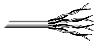
Twisted pair cabling comes in two varieties: shielded and unshielded. Unshielded twisted pair (UTP) is the most popular and is generally the best option for school networks 
 Unshielded twisted pair
The quality of UTP may vary from telephone-grade wire to extremely high-speed cable. The cable has four pairs of wires inside the jacket. Each pair is twisted with a different number of twists per inch to help eliminate interference from adjacent pairs and other electrical devices. The tighter the twisting, the higher the supported transmission rate and the greater the cost per foot. The EIA/TIA (Electronic Industry Association/Telecommunication Industry Association) has established standards of UTP and rated six categories of wire (additional categories are emerging).

Categories of Unshielded Twisted Pair

CategorySpeedUse
11 MbpsVoice Only (Telephone Wire)
24 MbpsLocalTalk & Telephone (Rarely used)
316 Mbps10BaseT Ethernet
420 MbpsToken Ring (Rarely used)
5100 Mbps (2 pair)100BaseT Ethernet
1000 Mbps (4 pair)Gigabit Ethernet
5e1,000 MbpsGigabit Ethernet
610,000 MbpsGigabit Ethernet


Unshielded Twisted Pair Connector

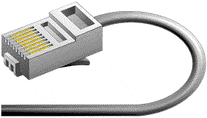
The standard connector for unshielded twisted pair cabling is an RJ-45 connector. This is a plastic connector that looks like a large telephone-style connector . A slot allows the RJ-45 to be inserted only one way. RJ stands for Registered Jack, implying that the connector follows a standard borrowed from the telephone industry. This standard designates which wire goes with each pin inside the connector.
 RJ-45 connector

Shielded Twisted Pair (STP) Cable

Although UTP cable is the least expensive cable, it may be susceptible to radio and electrical frequency interference (it should not be too close to electric motors, fluorescent lights, etc.). If you must place cable in environments with lots of potential interference, or if you must place cable in extremely sensitive environments that may be susceptible to the electrical current in the UTP, shielded twisted pair may be the solution. Shielded cables can also help to extend the maximum distance of the cables.
Shielded twisted pair cable is available in three different configurations:
  1. Each pair of wires is individually shielded with foil.
  2. There is a foil or braid shield inside the jacket covering all wires (as a group).
  3. There is a shield around each individual pair, as well as around the entire group of wires (referred to as double shield twisted pair).

Coaxial Cable

Coaxial cabling has a single copper conductor at its center. A plastic layer provides insulation between the center conductor and a braided metal shield . The metal shield helps to block any outside interference from fluorescent lights, motors, and other computers.
 Coaxial cable
Although coaxial cabling is difficult to install, it is highly resistant to signal interference. In addition, it can support greater cable lengths between network devices than twisted pair cable. The two types of coaxial cabling are thick coaxial and thin coaxial.
Thin coaxial cable is also referred to as thinnet. 10Base2 refers to the specifications for thin coaxial cable carrying Ethernet signals. The 2 refers to the approximate maximum segment length being 200 meters. In actual fact the maximum segment length is 185 meters. Thin coaxial cable has been popular in school networks, especially linear bus networks.
Thick coaxial cable is also referred to as thicknet. 10Base5 refers to the specifications for thick coaxial cable carrying Ethernet signals. The 5 refers to the maximum segment length being 500 meters. Thick coaxial cable has an extra protective plastic cover that helps keep moisture away from the center conductor. This makes thick coaxial a great choice when running longer lengths in a linear bus network. One disadvantage of thick coaxial is that it does not bend easily and is difficult to install.

Coaxial Cable Connectors

The most common type of connector used with coaxial cables is the Bayone-Neill-Concelman (BNC) connector . Different types of adapters are available for BNC connectors, including a T-connector, barrel connector, and terminator. Connectors on the cable are the weakest points in any network. To help avoid problems with your network, always use the BNC connectors that crimp, rather screw, onto the cable.
 BNC connector

Fiber Optic Cable

Fiber optic cabling consists of a center glass core surrounded by several layers of protective materials (See fig. 5). It transmits light rather than electronic signals eliminating the problem of electrical interference. This makes it ideal for certain environments that contain a large amount of electrical interference. It has also made it the standard for connecting networks between buildings, due to its immunity to the effects of moisture and lighting.
Fiber optic cable has the ability to transmit signals over much longer distances than coaxial and twisted pair. It also has the capability to carry information at vastly greater speeds. This capacity broadens communication possibilities to include services such as video conferencing and interactive services. The cost of fiber optic cabling is comparable to copper cabling; however, it is more difficult to install and modify. 10BaseF refers to the specifications for fiber optic cable carrying Ethernet signals.
The center core of fiber cables is made from glass or plastic fibers . A plastic coating then cushions the fiber center, and kevlar fibers help to strengthen the cables and prevent breakage. The outer insulating jacket made of teflon or PVC.
 Fiber optic cable
There are two common types of fiber cables -- single mode and multimode. Multimode cable has a larger diameter; however, both cables provide high bandwidth at high speeds. Single mode can provide more distance, but it is more expensive.
SpecificationCable Type
10BaseTUnshielded Twisted Pair
10Base2Thin Coaxial
10Base5Thick Coaxial
100BaseTUnshielded Twisted Pair
100BaseFXFiber Optic
100BaseBXSingle mode Fiber
100BaseSXMultimode Fiber
1000BaseTUnshielded Twisted Pair
1000BaseFXFiber Optic
1000BaseBXSingle mode Fiber
1000BaseSXMultimode Fiber

Installing Cable - Some Guidelines

When running cable, it is best to follow a few simple rules:

  • Always use more cable than you need. Leave plenty of slack.
  • Test every part of a network as you install it. Even if it is brand new, it may have problems that will be difficult to isolate later.
  • Stay at least 3 feet away from fluorescent light boxes and other sources of electrical interference.
  • If it is necessary to run cable across the floor, cover the cable with cable protectors.
  • Label both ends of each cable.
  • Use cable ties (not tape) to keep cables in the same location together.

PROXIES

     A proxy device (running either on dedicated hardware or as software on a general-purpose machine) may act as a firewall by responding to input packets (connection requests, for example) in the manner of an application, whilst blocking other packets.
proxy server
Proxies make tampering with an internal system from the external network more difficult, and misuse of one internal system would not necessarily cause a security breach exploitable from outside the firewall (as long as the application proxy remains intact and properly configured). Conversely, intruders may hijack a publicly-reachable system and use it as a proxy for their own purposes; the proxy then masquerades as that system to other internal machines. While use of internal address spaces enhances security, crackers may still employ methods such as IP spoofing to attempt to pass packets to a target network.

FIREWALLS

   In computing, a firewall is a piece of hardware and/or software which functions in a networked environment to prevent some communications forbidden by the security policy, analogous to the function of firewalls in building construction.

firewall
A firewall has the basic task of controlling traffic between different zones of trust. Typical zones of trust include the Internet (a zone with no trust) and an internal network (a zone with high trust). The ultimate goal is to provide controlled connectivity between zones of differing trust levels through the enforcement of a security policy and connectivity model based on the least privilege principle.
There are three basic types of firewalls depending on:

  1. whether the communication is being done between a single node and the network, or between two or more networks
  2. whether the communication is intercepted at the network layer, or at the application layer
  3. whether the communication state is being tracked at the firewall or not

With regard to the scope of filtered communication these firewalls are exist:
  1. Personal firewalls, a software application which normally filters traffic entering or leaving a single computer through the Internet.
  2. Network firewalls, normally running on a dedicated network device or computer positioned on the boundary of two or more networks or DMZs (demilitarized zones). Such a firewall filters all traffic entering or leaving the connected networks.
In reference to the layers where the traffic can be intercepted, three main categories of firewalls exist:


  1. network layer firewalls An example would be iptables.
  2. application layer firewalls An example would be TCP Wrapper.
  3. application firewalls An example would be restricting ftp services through /etc/ftpaccess file
These network-layer and application-layer types of firewall may overlap, even though the personal firewall does not serve a network; indeed, single systems have implemented both together.
There's also the notion of application firewalls which are sometimes used during wide area network (WAN) networking on the world-wide web and govern the system software. An extended description would place them lower than application layer firewalls, indeed at the Operating System layer, and could alternately be called operating system firewalls.
Lastly, depending on whether the firewalls track packet states, two additional categories of firewalls exist:

  1. stateful firewalls
  2. stateless firewalls

Network layer firewalls

Network layer firewalls operate at a (relatively low) level of the TCP/IP protocol stack as IP-packet filters, not allowing packets to pass through the firewall unless they match the rules. The firewall administrator may define the rules; or default built-in rules may apply (as in some inflexible firewall systems).
A more permissive setup could allow any packet to pass the filter as long as it does not match one or more "negative-rules", or "deny rules". Today network firewalls are built into most computer operating system and network appliances.
Modern firewalls can filter traffic based on many packet attributes like source IP address, source port, destination IP address or port, destination service like WWW or FTP. They can filter based on protocols, TTL values, netblock of originator, domain name of the source, and many other attributes.

Application-layer firewalls

Application-layer firewalls work on the application level of the TCP/IP stack (i.e., all browser traffic, or all telnet or ftp traffic), and may intercept all packets traveling to or from an application. They block other packets (usually dropping them without acknowledgement to the sender). In principle, application firewalls can prevent all unwanted outside traffic from reaching protected machines.
By inspecting all packets for improper content, firewalls can even prevent the spread of the likes of viruses. In practice, however, this becomes so complex and so difficult to attempt (given the variety of applications and the diversity of content each may allow in its packet traffic) that comprehensive firewall design does not generally attempt this approach

MODEMS & TRANSCEIVERS

Modems

A modem is a device that makes it possible for computers to communicate over telephone lines. The word modem comes from Modulate and Demodulate. Because standard telephone lines use analog signals, and computers digital signals, a sending modem must modulate its digital signals into analog signals. The computers modem on the receiving end must then demodulate the analog signals into digital signals.
modem
Modems can be external, connected to the computers serial port by an RS-232 cable or internal in one of the computers expansion slots. Modems connect to the phone line using standard telephone RJ-11 connectors.

Transceivers (media converters)

Transceiver short for transmitter-receiver, a device that both transmits and receives analog or digital signals. The term is used most frequently to describe the component in local-area networks (LANs) that actually applies signals onto the network wire and detects signals passing through the wire. For many LANs, the transceiver is built into the network interface card (NIC). Some types of networks, however, require an external transceiver.
transeiver
In Ethernet networks, a transceiver is also called a Medium Access Unit (MAU). Media converters interconnect different cable types twisted pair, fiber, and Thin or thick coax, within an existing network. They are often used to connect newer 100-Mbps, Gigabit Ethernet, or ATM equipment to existing networks, which are generally 10BASE-T, 100BASE-T, or a mixture of both. They can also be used in pairs to insert a fiber segment into copper networks to increase cabling distances and enhance immunity to electromagnetic interference (EMI).

WAP-WIRELESS ACCESS POINT

         
        A wireless network adapter card with a transceiver sometimes called an access point, broadcasts and receives signals to and from the surrounding computers and passes back and forth between the wireless computers and the cabled network.
wireless access point
Access points act as wireless hubs to link multiple wireless NICs into a single subnet. Access points also have at least one fixed Ethernet port to allow the wireless network to be bridged to a traditional wired Ethernet network.

ISDN - Integrated Services Digital Network

       Integrated Services Digital Network adapters can be used to send voice, data, audio, or video over standard telephone cabling. ISDN adapters must be connected directly to a digital telephone network. ISDN adapters are not actually modems, since they neither modulate nor demodulate the digital ISDN signal.
Like standard modems, ISDN adapters are available both as internal devices that connect directly to a computer's expansion bus and as external devices that connect to one of a computer's serial or parallel ports. ISDN can provide data throughput rates from 56 Kbps to 1.544 Mbps (using a T1 carrier service).
isdn adpator
ISDN hardware requires a NT (network termination) device, which converts network data signals into the signaling protocols used by ISDN. Some times, the NT interface is included, or integrated, with ISDN adapters and ISDN-compatible routers. In other cases, an NT device separate from the adapter or router must be implemented. ISDN works at the physical, data link, network, and transport layers of the OSI Model.

NETWORK INTERFACE CARD

     Network Interface Card, or NIC is a hardware card installed in a computer so it can communicate on a network. The network adapter provides one or more ports for the network cable to connect to, and it transmits and receives data onto the network cable.

Wireless Lan card
wireless lan card
Every networked computer must also have a network adapter driver, which controls the network adapter. Each network adapter driver is configured to run with a certain type of network adapter.
Network card
networkcard
Network Interface Adapter Functions 
Network interface adapters perform a variety of functions that are crucial to getting data to and from the computer over the network.
These functions are as follows:
Data encapsulation
The network interface adapter and its driver are responsible for building the frame around the data generated by the network layer protocol, in preparation for transmission. The network interface adapter also reads the contents of incoming frames and passes the data to the appropriate network layer protocol.
Signal encoding and decoding
The network interface adapter implements the physical layer encoding scheme that converts the binary data generated by the network layer-now encapsulated in the frame-into electrical voltages, light pulses, or whatever other signal type the network medium uses, and converts received signals to binary data for use by the network layer.
transmission and reception
The primary function of the network interface adapter is to generate and transmit signals of the appropriate type over the network and to receive incoming signals. The nature of the signals depends on the network medium and the data-link layer protocol. On a typical LAN, every computer receives all of the packets transmitted over the network, and the network interface adapter examines the destination address in each packet, to see if it is intended for that computer. If so, the network interface adapter passes the packet to the computer for processing by the next layer in the protocol stack; if not, the network interface adapter discards the packet.
Data buffering 
Network interface adapters transmit and receive data one frame at a time, so they have built-in buffers that enable them to store data arriving either from the computer or from the network until a frame is complete and ready for processing.
Serial/parallel conversion
The communication between the computer and the network interface adapter runs in parallel, that is, either 16 or 32 bits at a time, depending on the bus the adapter uses. Network communications, however, are serial (running one bit at a time), so the network interface adapter is responsible for performing the conversion between the two types of transmissions.
Media access control
The network interface adapter also implements the MAC mechanism that the data-link layer protocol uses to regulate access to the network medium. The nature of the MAC mechanism depends on the protocol used.

Network protocols

A networked computer must also have one or more protocol drivers (sometimes called a transport protocol or just a protocol). The protocol driver works between the upper-level network software and the network adapter to package data to be sent on the network.
In most cases, for two computers to communicate on a network, they must use identical protocols. Sometimes, a computer is configured to use multiple protocols. In this case, two computers need only one protocol in common to communicate. For example, a computer running File and Printer Sharing for Microsoft Networks that uses both NetBEUI and TCP/IP can communicate with computers using only NetBEUI or TCP/IP.

DYNAMIC ROUTING

 The chief advantages of dynamic routing over static routing are scalability and adaptability. A dynamically routed network can grow more quickly and larger, and is able to adapt to changes in the network topology brought about by this growth or by the failure of one or more network components.
With a dynamic routing protocol, routers learn about the network topology by communicating with other routers. Each router announces its presence, and the routes it has available, to the other routers on the network. Therefore, if you add a new router, or add an additional segment to an existing router, the other routers will hear about the addition and adjust their routing tables accordingly. You don't have to reconfigure the routers to tell them that the network has changed. Similarly, if you move a network segment, the other routers will hear about the change. You only need to change the configuration of the router (or routers) that connect the segment that moved. This reduces the chance that errors will occur.
The ability to learn about changes to the network's configuration has implications beyond adding new segments or moving old ones. It also means that the network can adjust to failures. If a network has redundant paths, then a partial network failure appears to the routers as if some segments got moved (they are now reached via alternate paths), and some segments have been removed from the network (they are now unreachable). In short, there's no real difference between a network failure and a configuration change. Dynamic routing allows the network to continue functioning, perhaps in a degraded fashion, when a partial failure occurs.


Disadvantages of Dynamic Routing

   I would be a liar if I told you that dynamic routing has no disadvantages. Chief among the disadvantages is an increase in complexity. Communicating information about network topology is not as simple as saying, "Hey, I can reach the following destinations..." Each router participating in the dynamic routing protocol must decide exactly what information to send to other routers; more important, it must attempt to select the best route for reaching other destinations from the candidates it learns about from other routers. In addition, if a router is going to adapt to changes in the network, it must be prepared to remove old or unusable information from its routing table. How it determines what is old or unusable adds to the complexity of the routing protocol. Unfortunately, the better a protocol handles the various different situations in a network, the more complex it is likely to be. This complexity tends to lead to errors in the protocol's implementation, or differences in how vendors interpret the protocol.
In order to communicate information about the topology of the network, routers must periodically send messages to each other using a dynamic routing protocol. These messages must be sent across network segments just like any other packets. But unlike other packets in the network, these packets do not contain any information to or from a user. Instead, they contain information that is only useful to the routers. Thus, from the users' point of view, these packets are pure overhead. On a low-speed link, these messages can consume much of the available bandwidth, especially if the network is large or unstable.
Finally, some or all of the machines in a network may be unable to speak any dynamic routing protocol, or they may not speak a common protocol. If that is the case, static routing may be your only option.
With all the disadvantages listed of both static and dynamic routing, you may be wondering what the best choice is. Only you can say for sure what is best for your network, but there is a reasonable middle ground that limits the complexity of dynamic routing without sacrificing its scalability. This middle ground is a hybrid scheme, in which part of the network uses static routing and part uses dynamic routing.